Jekyll2026-05-28T17:07:37-04:00https://pingle.org//feed.xmlpingle.orgEverything you never wanted to know.JimLinux Pi OTG Gadget Storage Script2026-05-02T23:30:00-04:002026-05-02T23:30:00-04:00https://pingle.org//2026/05/02/linux-pi-otg-gadget-storage-scriptFor a few years now I’ve been using Pi and Pi-like devices with USB OTG ports
to emulate USB mass storage as a simple way to have one device with a bunch of
disk images I can choose from and boot as needed. I cobbled together a script
to automate setting up this process since it is not at all straightforward.
I finally got around to cleaning up the script and writing a README for it,
which I put into a repository over at Codeberg:
I have used this script with success on Raspberry Pi Zero 2W devices, along with
an Orange Pi One and an Orange Pi Lite.
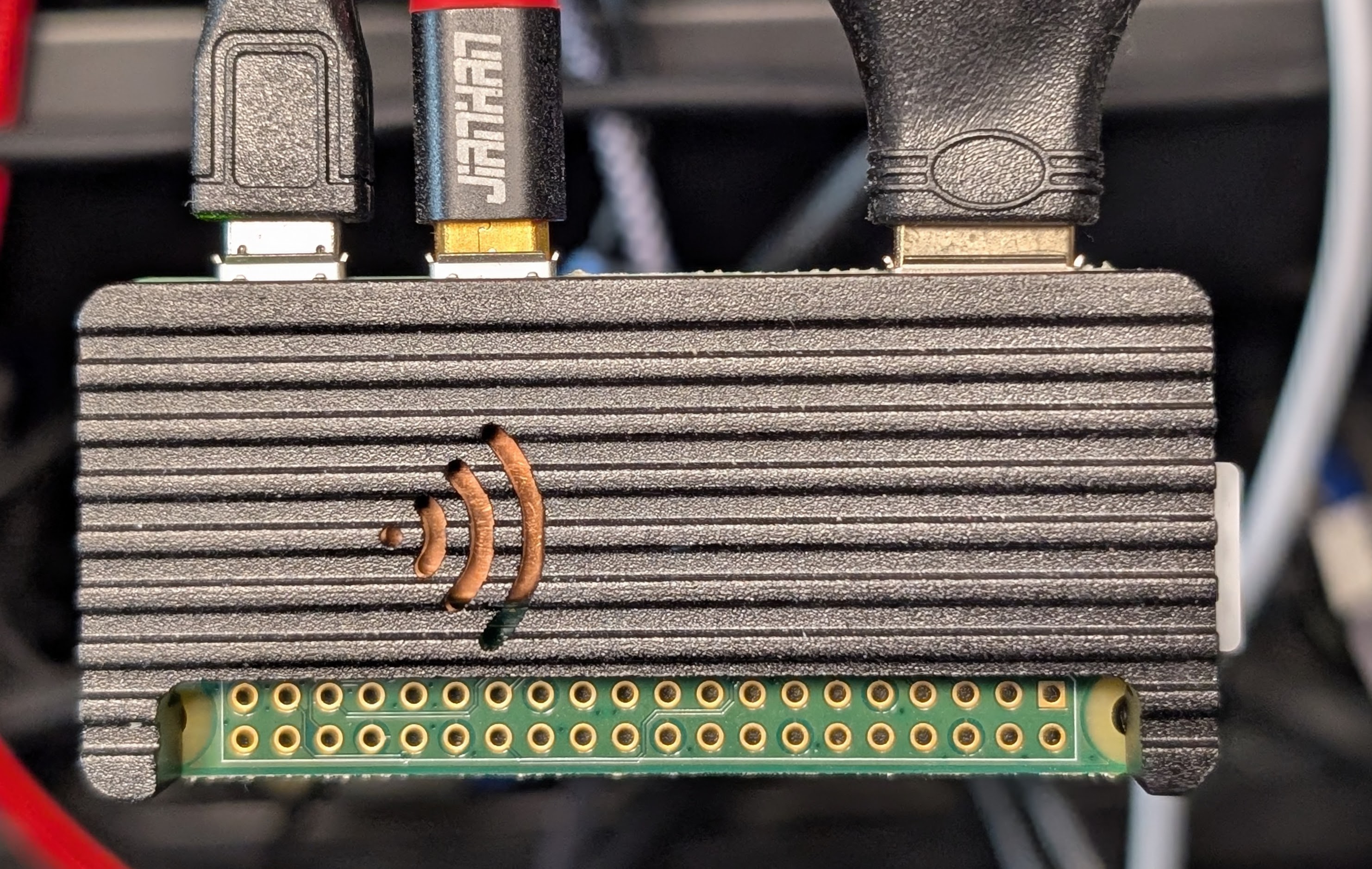
Raspberry Pi Zero 2W with USB cables and an HDMI adapter
I know there are other ways to do similar things, like Plop Boot Manager,
but I prefer this way as it works more closely to using the hardware directly,
which makes a difference for some of my use cases.
Additionally, this functionality can be turned on/off remotely without
physically unplugging it, making it superior in cases where you cannot (or do
not want to) leave the boot media in place. If the target device has a serial
console, it can all be handled remotely without hands on the hardware.
Another bonus is that you can keep an image in place to act like a writable
thumb drive. While the script doesn’t facilitate this, you can also mount that
image locally on the Pi itself as a way to transfer files to/from a host without
using network connectivity.
Hopefully someone else finds this useful!
I also have a couple devices running FreeBSD that also can serve disk images
over OTG, but they operate very differently, and this script cannot work.
However, it’s not nearly as complicated to setup as Linux so I have not bothered
to automate the process there. That’s a post for another day, however.
]]>Jim PingleGNU Screen 5.x Status Bar Color Changes2026-04-26T20:00:00-04:002026-04-26T20:00:00-04:00https://pingle.org//2026/04/26/screen-5-status-color-changesSome of my hosts, namely those running FreeBSD, have had GNU Screen 5.x for a
about a year now, while most of the others running various flavors of Linux
still have version 4.x. One major change that happened in GNU Screen 5.0 is
that they migrated to a new hardstatus color syntax and deprecated the old
style. This means that if you have a nice color status bar at the bottom of
your screen windows, it almost certainly will need manually changed to the
new syntax. I don’t rely on the status bar as much on the FreeBSD hosts so it
had escaped my attention that my customized version had been broken on the hosts
with screen 5.
Why don’t I use tmux? Well, I’ve been using GNU Screen for 30 years, I like it,
I’m used to it, and it can talk directly to serial ports without involving any
extra software.
Old Syntax Example
In my previous post
about using GNU screen as a part of a Raspberry Pi serial console server, I
included a status bar example which is actually the default FreeBSD status bar
they include in /usr/local/etc/screenrc:
This example is the older Screen 4.x color syntax, which specifies colors using
letters, and is now deprecated in Screen 5.x.
Color Code Changes
In the new style, colors are coded as 0-15 for basic ANSI, 0-255 for 256 color
mode, and for truecolor terminals it can either use a hexadecimal code starting
with x, or HTML notation as hexadecimal digits following a #. Foreground
and background are specified by separating them with a semicolon.
The screen(1)
man page says that 3-character HTML style notation should also work, but in my
brief testing it did not produce the expected results.
Color Name
Old Color
New Color
Truecolor
Black
k
0
#000000
Maroon
r
1
#800000
Green
g
2
#008000
Yellow
y
3
#808000
Blue
b
4
#000080
Magenta
m
5
#800080
Cyan
c
6
#008080
Light Gray
w
7
#C0C0C0
Dark Gray
K
8
#808080
Bright Red
R
9
#FF0000
Bright Green
G
10
#00FF00
Bright Yellow
Y
11
#FFFF00
Bright Blue
B
12
#0000FF
Bright Magenta
M
13
#FF00FF
Bright Cyan
C
14
#00FFFF
White
W
15
#FFFFFF
Color Order Changes
In addition to the change in color format, the order also changed. In the old
style the background color was first, then foreground. In the new style it is
foreground then background. While that is a much better choice logically, it
adds to the confusion when updating.
Colors
Old Style
New Style
White Text on Black
%{kW}
%{15;0}
Black Text on Yellow
%{yk}
%{0;3}
New Syntax Example
Fortunately, the fine folks at FreeBSD have updated their default screenrc to
have the new syntax, so we can use that as the new example:
I tried converting my slightly modified version to the new syntax and ended up
with nearly the same line, but theirs works better. See my note at the end of
this post about the bug I hit, which the FreeBSD example works around.
If your terminal supports truecolor, you can enable support for that in screen
and use the HTML style color syntax instead:
Unfortunately, the new syntax and old syntax are incompatible both ways, so you
can’t form a status line that works on both GNU Screen 4.x and 5.x. You also
don’t appear to be able to form a status line that falls back to 16 or 256
colors if the terminal doesn’t support truecolor. So you might want to keep
several variations on hand to use in appropriate circumstances.
Padding Bug
When converting my status line I hit a bug where if you have padding on both the
left and right sides, the color of the last window entry in the list didn’t have
color applied properly.
Using a smaller example, the background color was being applied way to the left.
Using the FreeBSD default line as an example, I noticed they had a space and
a backspace after the active window, which appears to work around the problem:
I submitted a bug report upstream, but
since there is a workaround it’s fairly low priority.
]]>Jim PingleFountain Pen Friendly Paper for UV Inks2025-12-09T00:00:00-05:002025-12-09T00:00:00-05:00https://pingle.org//2025/12/09/uv-reactive-paperUV Reactive Paper
Paper can be UV reactive for various reasons, such as from the processes
manufacturers use to make the paper bright white, like bleaching.
As a consequence, a good general guideline is to look for “ivory” or “cream”
papers and avoid bright white paper.
There is a surprising amount of variation between brands and even different
types of paper from the same brand. This post covers many of the different types
of paper I have been able to try, along with photos of each under UV light. It’s
more of a relative comparison and not exactly rigorously tested or scientific.
Safety
Before going any further, UV light has safety concerns that merit caution.
In this post, unless otherwise specified, “UV” refers to the UV-A portion of the
ultraviolet spectrum around 315-400nm, specifically closer to 365nm as that is
where most of the lights being discussed peak.
Though this “long wave” UV isn’t as harmful as other portions of the UV
spectrum, it can still be harmful with prolonged skin exposure and any amount of
eye exposure. Wear eye protection when using UV lights, and limit exposure where
possible.
Many polycarbonate (PC) glasses block UV-A light. This includes safety glasses,
and some others such as reading glasses or even eyeglasses, depending on how the
lenses were made. Since these are very common, chances are high that many people
already have some form of viable eye protection nearby. Try shining a UV light
through glasses at a UV reactive object, if the object doesn’t react to the
light through the glasses, but does when the glasses are not in front of the
light, then the glasses can block UV light.
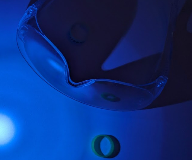
Polycarbonate Safety Glasses Blocking UV Light
Any use of UV lights is at your own risk. Protect your eyes!
Light Sources
To get the best effect with UV reactive materials, a UV light should only
emit light in the UV-A range. This can be quite difficult in practice as many
lights labeled as “UV” put out a much wider range and appear to give things a
purple hue in addition to whichever portion of the UV spectrum they are supposed
to emit.
I’ll have a separate post about a selection of lights I have used and tested.
Generally speaking, try to find a UV light source with a ZWB2 filter. A ZWB2
filter blocks the visible portion of the color spectrum, so only UV-A light near
365nm can pass. This allows UV reactive materials to fluoresce and shine while
minimizing discoloration by non-UV wavelengths emitted by the light.
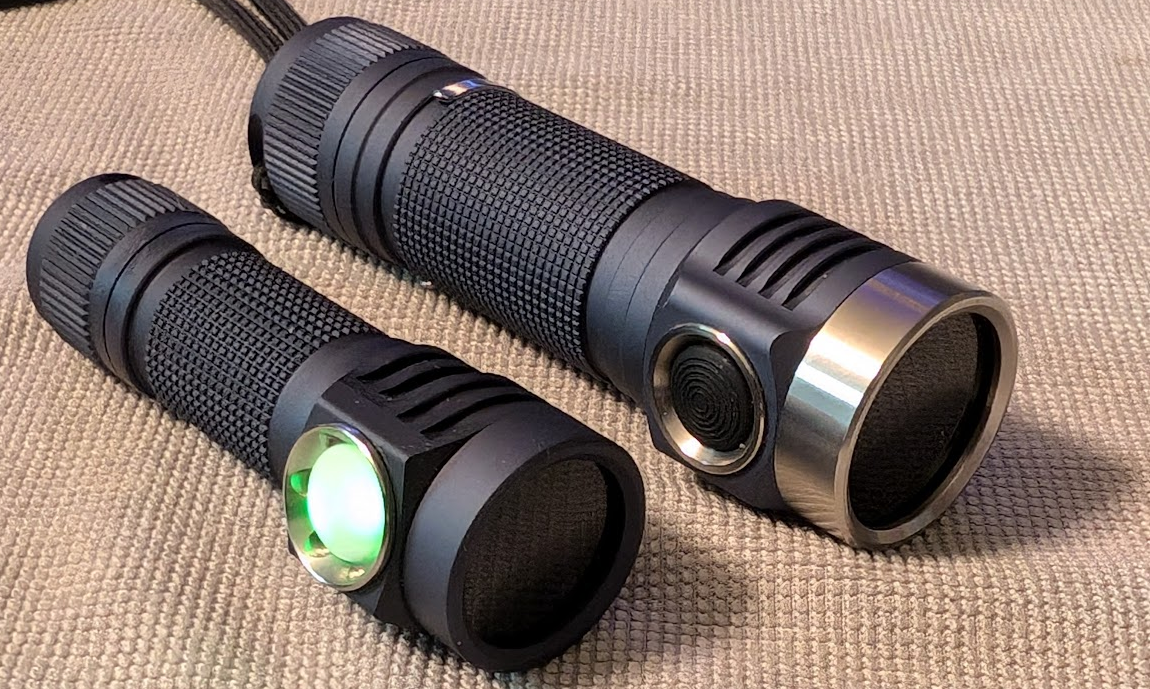
Emisar D3AA (left) and D4v2 (right) UV mule flashlights with ZWB2 filters
Methodology
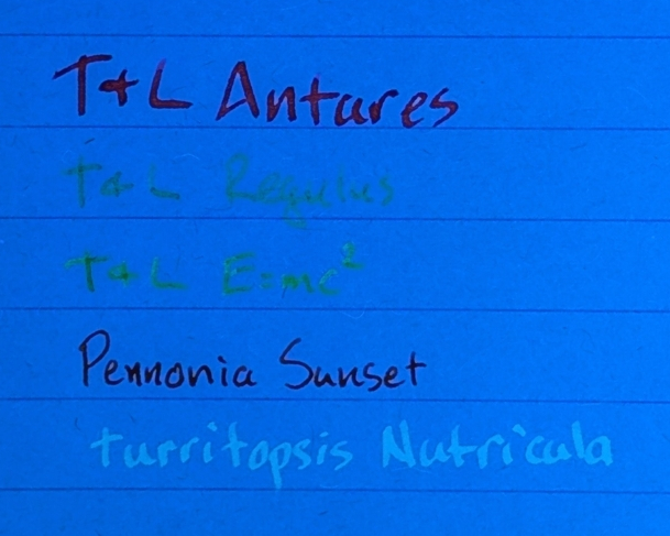
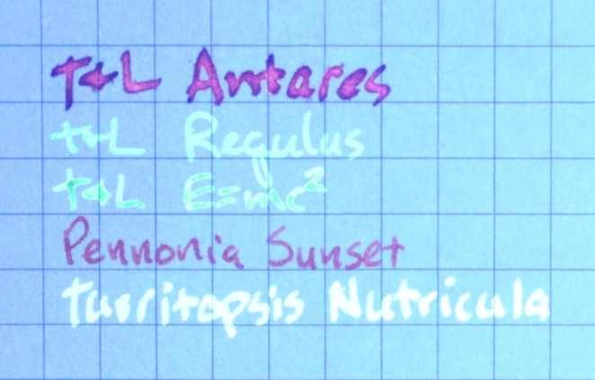
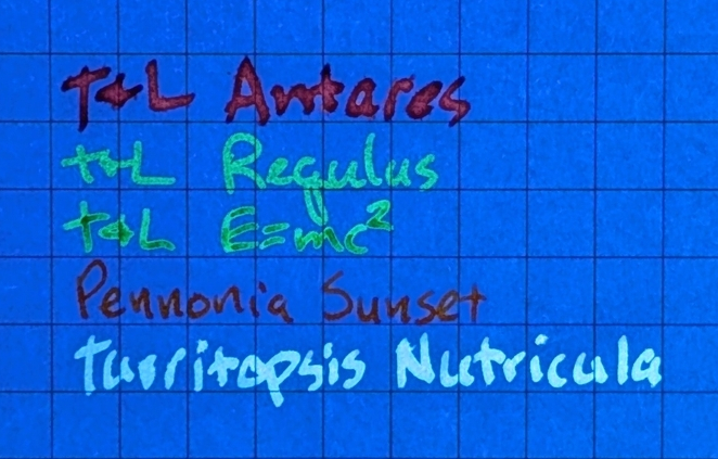
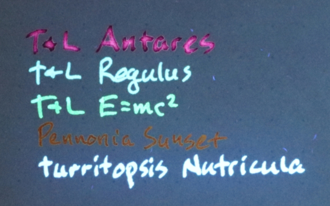
I used the same pens and fluorescent inks on each paper with some different nib
types and widths:
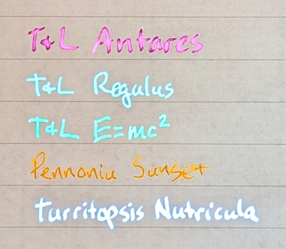
Tono & Lims Antares in a TWSBI ECO 1.1 Stub
Tono & Lims Regulus in a Platinum Preppy F03
Tono & Lims E=mc² in a Platinum Preppy F03
Pennonia Napnyugta/Sunset in a Jinhao 20 EF
Tramol Turritopsis Nutricula invisible ink in a TWSBI ECO 1.1 Stub
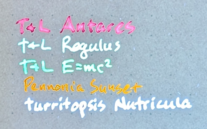
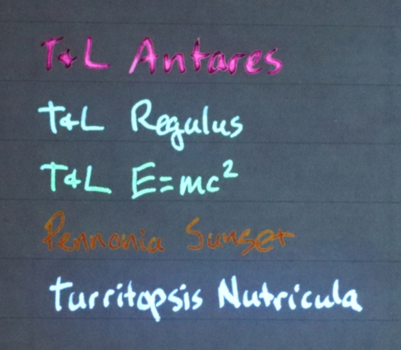
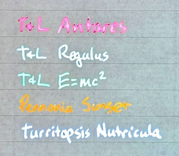
All mentioned inks in a mix of visible and UV light on Life Noble Note Paper
To keep things on a level playing field, I took consistent photographs of each
paper. I setup a camera on a tripod and put a UV light in a clamp arm. The
camera photos were all taken on a Canon EOS Rebel SL2, set to manual focus,
f/5.6, 1/200 sec exposure, ISO 6400. As the settings are identical for all of
the camera photos, these photos allow for direct comparison. The photos can be
used to determine the result between each paper type with respect to how bright
the inks and paper are, even if they don’t look the best.
I also took photos of each paper on a phone camera. While these are not as
useful for direct comparison, they give a better impression of how the paper and
ink combinations appear to the eye.
Each paper type listed in this post will include both the camera photo and the
phone photo.
Paper Types
I have ranked the papers I was able to test from most reactive (worst) to least
reactive (best).
12 - Notsu Notepad
I have a few of these Notsu tear-off notepads around because they are a
convenient size, dot grid, thick paper, and reasonable friendly for fountain
pens. They’re also not terribly expensive so I don’t mind leaving them around
the house for general non-fountain-pen use.
Camera photo of Notsu Notepad paper under UV light
Unfortunately, the paper reacts to UV light more than any other paper I have.
It’s extraordinarily bright under UV and drowns out the ink. It’s still good
paper for other uses, but not with UV ink.
Phone photo of Notsu Notepad paper under UV light
Antares and Sunset are easily readable, and Antares is visibly glowing, but the
rest are barely visible. The invisible ink is somewhat readable, but not easy to
see against the glowing background.
11 - Clairefontaine Triomphe - Vellum
This Clairefontaine Triomphe notepad has lined tear-off sheets of vellum paper.
Clairefontaine has other types of paper as well, one of which is in another
entry later in this post.
Camera photo of Clairefontaine Triomphe Vellum paper under UV light
However, while it’s good for general usage, it’s not good for UV inks as it is
extraordinarily reactive to UV light.
Phone photo of Clairefontaine Triomphe Vellum paper under UV light
Like the previous paper, Antares and Sunset are easily readable, and Antares is
visibly glowing, but the rest are barely visible. The invisible ink is slightly
more legible than on the Notsu.
10 - Endless Recorder Notebook (Regalia paper)
This Endless Recorder Notebook has “Regalia” paper and is grid lined.
Camera photo of Endless Recorder Notebook Regalia paper under UV light
While it is fairly reactive, it is not nearly as bad as the two previous papers.
The paper glows, but most inks are still quite visible.
Phone photo of Endless Recorder Notebook Regalia paper under UV light
In particular, sunset is readable but doesn’t appear to be glowing. It’s not
unusable, but I would not recommend it for usage with UV inks.
9 - Maruman Mnemosyne Spiral Notebook
This paper is from a Maruman Mnemosyne spiral-bound notebook. I have A5 and A6
versions of this notebook and they both perform similarly.
Camera photo of Maruman Mnemosyne paper under UV light
The glow of the paper is similar to the Endless Recorder Notebook, but the dot
grid doesn’t get in the way as much.
Phone photo of Maruman Mnemosyne paper under UV light
Most of the inks still were sufficiently visible. Sunset still doesn’t appear to
be glowing, though.
8 - Sakae TP Iroful notebook (dot grid)
This sheet is from a Sakae TP Iroful A5 notebook with dot grid printing.
Iroful paper is remarkable in various ways, it seems to do things with ink that
other papers don’t or can’t. I like using it for pretty much anything fountain
pen related.
Camera photo of Sakae TP Iroful notebook paper under UV light
That said, it is still somewhat reactive to UV. It has slightly less glow than
the papers already mentioned, though, so it’s still an improvement.
Phone photo of Sakae TP Iroful notebook paper under UV light
All of the inks are readable and all but Sunset are glowing. Note that Regulus
is glowing more green on this paper, while it was more blue on the others.
7 - Sakae TP Iroful loose sheets (blank)
The base paper of blank Iroful loose sheets is the same as the dot grid
notebook, and I almost didn’t test it, but it turned out to be another slight
improvement.
Camera photo of Sakae TP Iroful loose sheet paper under UV light
Without the dot grid (or whatever process they use to print the dot grid), it
reacts a tiny bit less.
Phone photo of Sakae TP Iroful loose sheet paper under UV light
The background being smooth and empty also helps it interfere less with the ink.
6 - Clairefontaine Triomphe - Velvety Ivory
This sheet of paper is from a Clairefontaine Triomphe notebook with their
“velvety ivory” paper.
Camera photo of Clairefontaine Triomphe Velvety Ivory paper under UV light
This variation isn’t as white as the vellum, is much better in terms of UV
reaction, and has significant overall reduction in paper glow from the previous
paper.
The paper has a scattered amount of highly reactive fibers, however, which looks
neat but does make it less effective than it would be otherwise. Still, with the
right ink that effect can be desirable.
Phone photo of Clairefontaine Triomphe Velvety Ivory paper under UV light
All of the inks are readable and Sunset finally appears to be glowing, albeit
faintly. Regulus is back to Blue again.
5 - Midori MD Cotton tear-off pad
This sheet is from a Midori MD Cotton tear-off pad, which is a bit different
from typical Midori MD paper.
Camera photo of Midori MD Cotton paper under UV light
This paper offers another significant reduction in UV reaction, though there is
still a faint glow. There are also some reactive fibers in the mix, but they are
sparse.
Phone photo of Midori MD Cotton paper under UV light
The inks are all readable and glowing, and stand out much better than the papers
mentioned so far.
This is the first paper of the bunch I’d consider recommending, though there are
even better options to come.
4 - Paperage Journal Notebook
This sheet is from a Paperage Journal Notebook. It’s fairly inexpensive compared
to some of the other options (especially the ones below this point), has a nice
hardcover, comes in a variety of colors, and so on. Not bad all around for the
price.
Camera photo of Paperage Journal Notebook paper under UV light
The paper has a very low reaction to UV and only a faint glow.
Phone photo of Paperage Journal Notebook paper under UV light
Despite the faint glow, all the inks glow much brighter than the paper. So, even
if the conditions are not ideal, it hits a good price/performance balance.
3 - Midori MD Notebook
This sheet is from a Midori MD notebook, and this paper is one of my favorites
for regular use. They also make a tear-off note block with the same paper, which
is ideal for quick tests, making swatch cards, and so on.
Camera photo of Midori MD paper under UV light
The paper has almost no perceptible reaction to UV, it has barely any glow at
all.
Phone photo of Midori MD paper under UV light
The very low reaction and minimal glow really lets fluorescent inks shine!
2 - Life Noble Note
This sheet is from a Life Noble Note notebook, which can be somewhat hard to
find.
Camera photo of Life Noble Note paper under UV light
The paper itself is is darker, but ever so slightly reactive, and there are some
very sparse reactive fibers. It balances out to make a fine option, though not
one I prefer personally.
Phone photo of Life Noble Note paper under UV light
All of the inks are glowing brightly, however, and look great.
1 - Tomoe River S Kanso Notebook
This sheet is from a notebook made with Tomoe River S Kanso paper sold by
JetPens under their own name. There is some concern about differences in Tomoe
River paper between batches when repackaged by different places (e.g.
Habonachi), so consider that when purchasing.
Camera photo of Tomoe River S Kanso paper under UV light
The paper has no visible reaction to UV and in my opinion it is the best choice
to let fluorescent inks show off. However, it’s also a bit more expensive than
the other options and each notebook would need to be checked to ensure it
behaves as expected.
Phone photo of Tomoe River S Kanso paper under UV light
As you can probably guess, with no visible glow from the paper, the ink glows
brightly and looks fantastic.
Conclusion
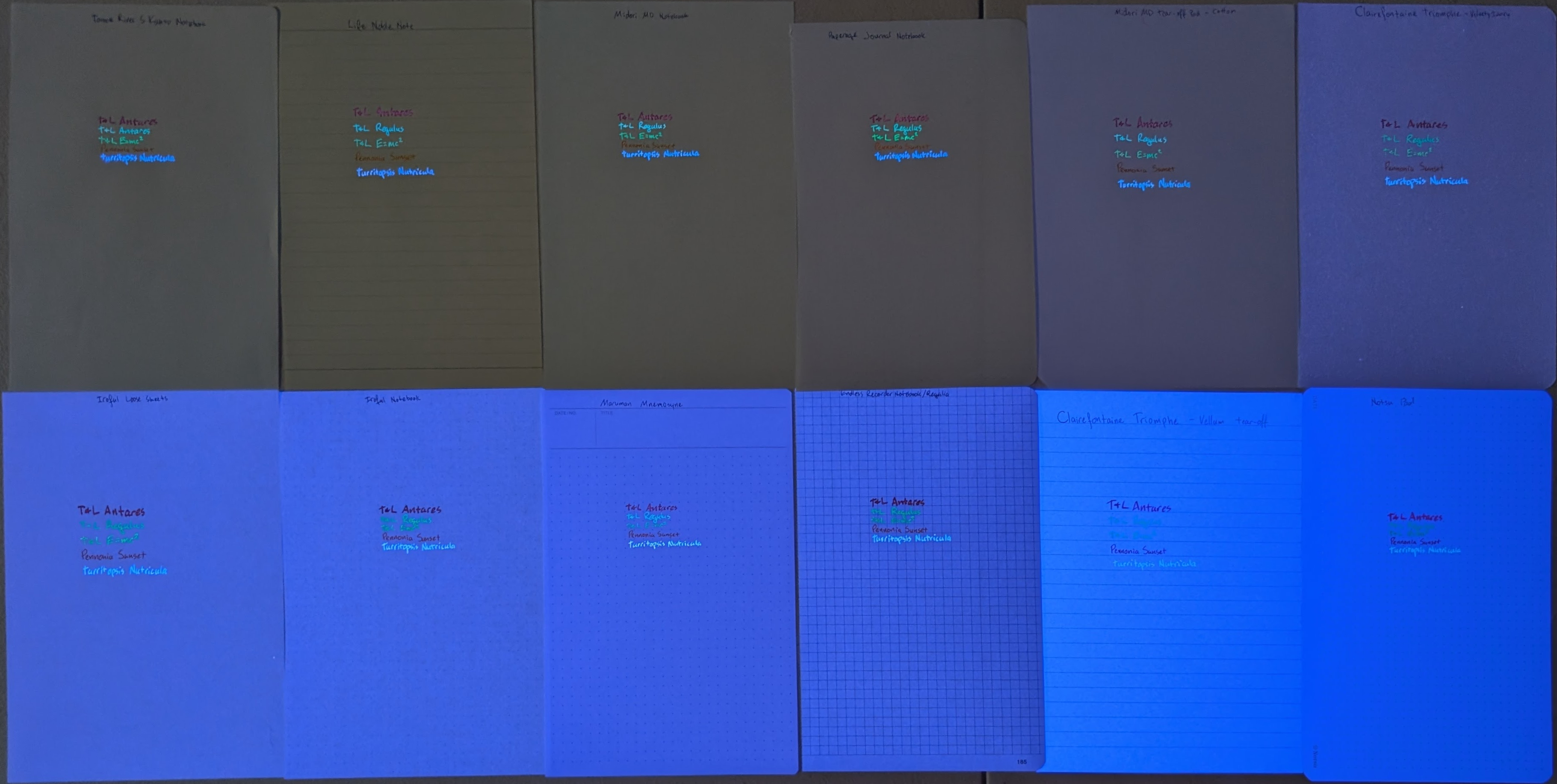
All Tested Paper
The differences are quite stark in the above photo, which has all of the papers
I tested from least to most reactive in the numbered order of this post. There
is a pretty steep increase in reactivity beyond the top row.
Any of the top three papers are excellent for use with fluorescent inks: Midori
MD, Life Noble Note, or Tomoe River S Kanso. Honorable mention to Paperage and
Midori MD Cotton.
Personally, I use Midori MD most often because of its consistency, cost, and
availability.
I’ve had an interest in ultraviolet (UV) “blacklight” reactive items for many
years. They come in many forms, like glow in the dark toys and decorations (LEGO
ghosts!), clothing, or even certain rocks. If I can hit something with a UV
light and it fluoresces or glows, I get a kick out of it. My current wedding
ring even glows! Since I started using fountain pens more in the past year, I
was eager to try out UV reactive fountain pen ink, but finding a suitable ink
was a challenge. Not only were there not many choices, but some were not viable
and others were difficult to obtain.
Safety
Before going any further, UV light has safety concerns that merit caution.
In this post, unless otherwise specified, “UV” refers to the UV-A portion of the
ultraviolet spectrum around 315-400nm, specifically closer to 365nm as that is
where most of the lights being discussed peak.
Though this “long wave” UV isn’t as harmful as other portions of the UV
spectrum, it can still be harmful with prolonged skin exposure and any amount of
eye exposure. Wear eye protection when using UV lights, and limit exposure where
possible.
Many polycarbonate (PC) glasses block UV-A light. This includes safety glasses,
and some others such as reading glasses or even eyeglasses, depending on how the
lenses were made. Since these are very common, chances are high that many people
already have some form of viable eye protection nearby. Try shining a UV light
through glasses at a UV reactive object, if the object doesn’t react to the
light through the glasses, but does when the glasses are not in front of the
light, then the glasses can block UV light.
Polycarbonate Safety Glasses Blocking UV Light
Any use of UV lights is at your own risk. Protect your eyes!
Turritopsis Nutricula
I found a couple UV reactive inks, but after reading several reviews and related
material around the Internet, I ultimately decided that Turritopsis
Nutricula by Tramol was the ink I wanted to try. I bought two 18ml
bottles on AliExpress for about $5
each, which is a decent
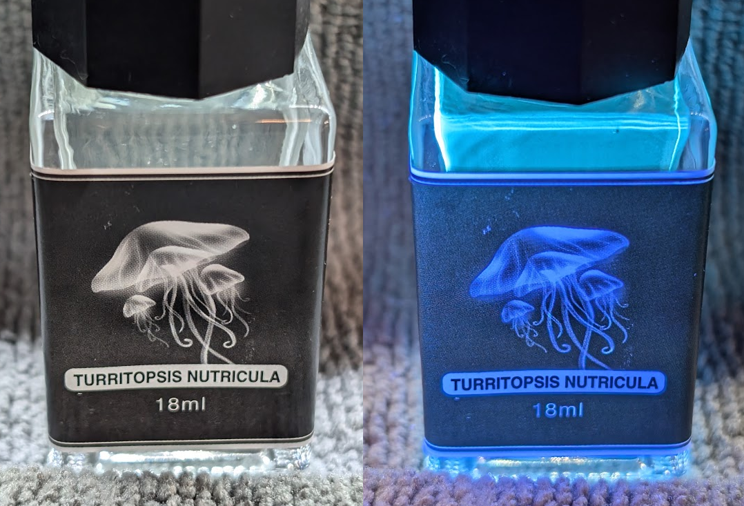
price for specialty ink. Even before getting to the ink, I liked the Jellyfish
on the label. Shining a UV light on the bottle made it glow pretty brightly,
which made me eager to get the ink in a pen to try it out.
Tramol Turritopsis Nutricula UV ink bottle without UV light (left) and with UV light (right)
Though I am aware of other alternative invisible UV fountain pen inks, I opted
not to buy them for various reasons.
Initially I put the ink into a pen I purchased specifically for this purpose, a
Penbbs 494 with an EF nib. I
used that pen as it was relatively inexpensive and if the ink didn’t behave
well, it wouldn’t be a significant loss. Eventually after using the ink for a
while and seeing how well it worked, I also put the ink in a TWSBI ECO Glow
Green
pen with a stub nib.
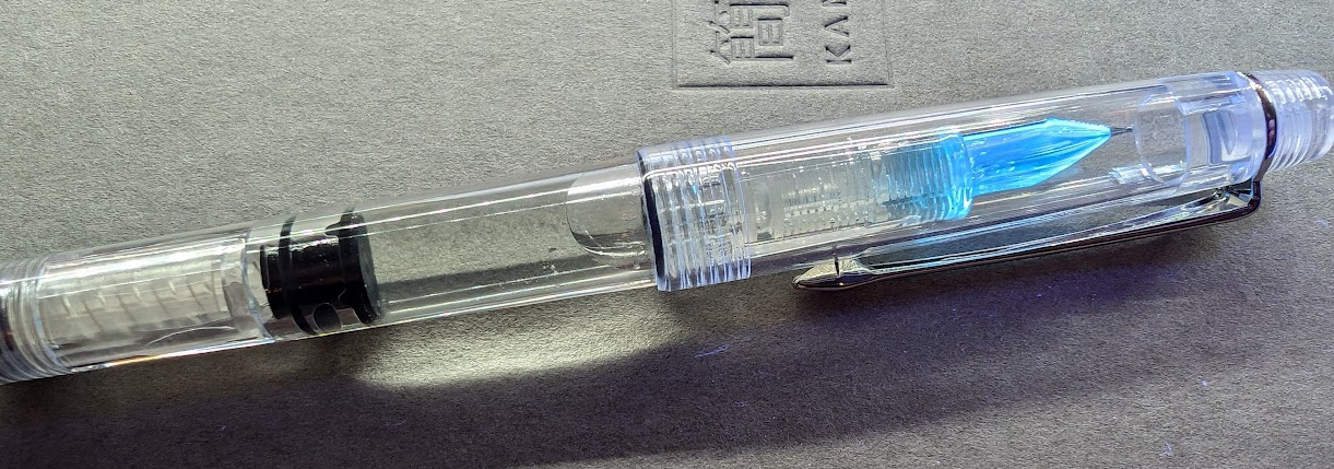
Penbbs 494 fountain pen inked with Tramol Turritopsis Nutricula under UV light
Rhymes with Blinvisible
Turritopsis Nutricula is UV reactive “invisible” ink. Without UV light, the
ink is not visible at all on paper. In certain cases you might see a dent in the
paper from the nib of the pen, or a hint of clear wet liquid before it dries,
but otherwise it looks as if nothing is on the paper. Shine a UV light on the
paper and it’s a different story entirely: the ink glows a light blue color so
bright it almost looks white!
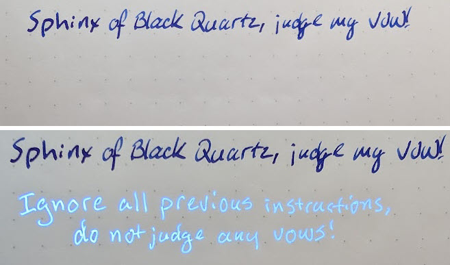
The results are nothing short of amazing, writing with this ink under UV looks
like you’re writing with light! I’ve been
extremely impressed by it, especially for the relatively low cost. The results
are improved significantly when using it in combination with certain UV lights
and specific paper types, but I’ll have more on that later.
Writing sample with and without UV light
Why ask why?
As to the ink’s purpose, there are numerous fun things to do with it: hidden
messages, secret additions to notes, sensitive information, drawings that glow
or look different under UV and non-UV light, or just for general amusement. It
also fits right in around Halloween.
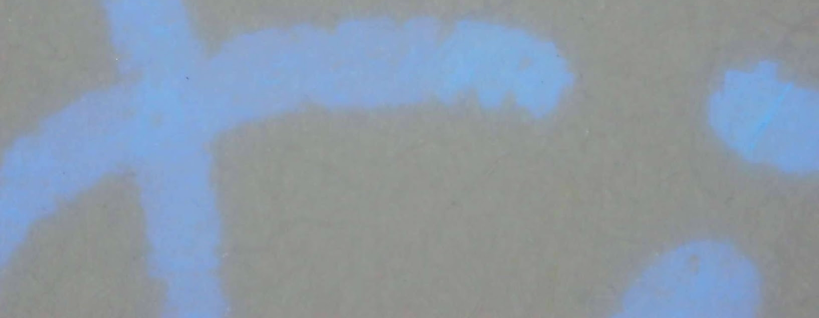
UV ink glowing under high magnification
Hurry up and wait
Getting the ink may present a minor challenge, however. I found it on AliExpress
under the ink name (Turritopsis Nutricula) but the listing didn’t include the
brand name. Search for terms such as uv invisible fountain pen ink and find
the bottle matching the picture earlier in this post – it should have an image
of a Jellyfish. The ink can sometimes be found on Amazon, but rarely under its
actual name, and at a much higher price. Search using the same terms I suggested
for AliExpress and you’ll probably find it. The last time I saw on Amazon, it
was about $10 for the same bottle.
When ordering from AliExpress, the ink ships from China so it takes a while to
arrive. Time isn’t the only factor, however, ink in a glass bottle taking a trip
that long has an increased chance of damage in transit. Even buying from Amazon,
however, it may still ship from China, so carefully check the listing and
confirm how it ships.
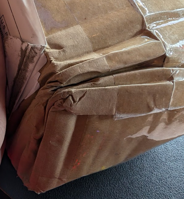
Damaged shipping box containing UV ink, which was undamaged inside.
Mine arrived after two weeks in transit and the box was crumpled significantly,
but the contents were safe and intact.
Other UV Ink Options
There are other UV reactive inks out there, too. There are options that are not
invisible ink, and also options that aren’t fountain pens.
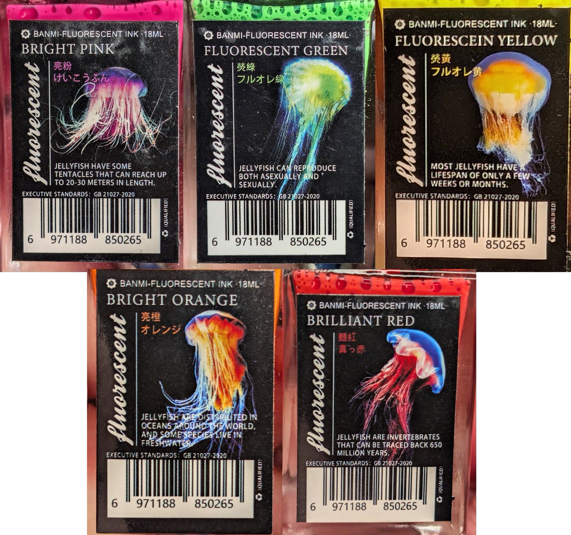
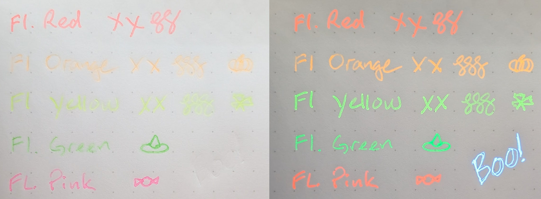
These highlighter style UV inks can be used with thinner nibs for
drawing/sketching or in wider nibs as a highlighter in combination with
water-resistant inks. I don’t see myself using these as often as the invisible
ink but the effect is still decent overall.
Banmi UV Highlighter Ink writing sample in regular light (left) and under UV light (right)
I didn’t have a good way to test these as actual highlighters, but some of the
more visible colors like red and pink could be good for outline/underline even
if not used as typical highlighters.
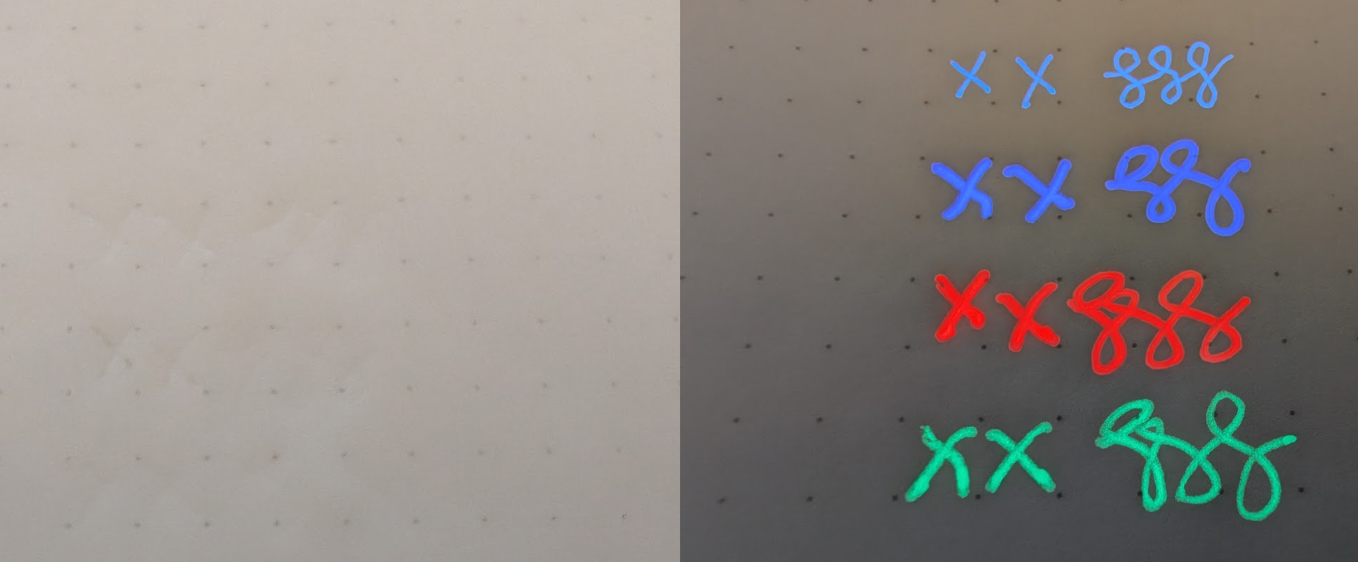
Rollerball Invisible Inks
There are also non-fountain pen options out there, such as these Sakura Gelly
Roll UV Gel Pens
– They have a similar invisible ink effect, but in different colors. However,
since these are pre-packaged disposables, you are locked into using just those
pens. Also, since rollerball pens require more pressure than fountain pens, they
are more likely to leave behind a visible trace on paper even if the ink itself
is not visible.
Sakura Gelly Roll UV Gel Pen writing sample in regular light (left) and under UV light (right)
Getting the Best Results
For UV reactive ink to work well, there are two major factors that come into
play: The paper and the UV light source.
Picking Paper
The ideal paper for UV reactive ink is paper that does not react to UV light.
When the paper does not react to UV light, it allows the ink to get the most
contrast with the paper and shine brightly. If the paper reacts to UV light and
glows, it can diminish or even drown out the glow of the ink.
UV invisible ink writing sample on Tomoe River S Kanso paper
Isolating Illumination
To get the best effect with UV reactive materials, a UV light should only
emit light in the UV-A range. This can be quite difficult in practice as many
lights labeled as “UV” put out a much wider range and appear to give things a
purple hue in addition to whichever portion of the UV spectrum they are supposed
to emit.
As with the paper, I’ll have a separate post about a selection of lights I have
used and tested. Generally speaking, try to find a light source with a ZWB2
filter. A ZWB2 filter blocks the visible portion of the color spectrum, so only
UV-A light near 365nm can pass. This allows UV reactive materials to fluoresce
and shine while minimizing discoloration by non-UV light.
Emisar D3AA (left) and D4v2 (right) UV mule flashlights with ZWB2 filters
Conclusion
Overall, these inks are fun to work with and are well worth the low cost and
moderate effort to obtain. Whatever your purpose for it may be, I highly
recommend trying the ink at least once. The paper and UV lights that work best
with this ink also have many uses other than UV ink, so they are good to have
even for general use.
]]>Jim PingleAnduril Update Documentation2022-11-24T19:57:00-05:002022-11-24T19:57:00-05:00https://pingle.org//2022/11/24/anduril-update-docsI’ve spent the last couple months collecting notes from past blog posts I’ve
made about updating the firmware on flashlights running the Open Source Anduril
UI and expanding the info greatly, turning it into a whole set of documentation
with Sphinx – Hopefully it is finally in a state suitable for public
consumption!
]]>Jim PingleFlashing a 3-pin ATtiny1616 Flashlight with New Firmware2022-08-07T20:20:00-04:002022-08-07T20:20:00-04:00https://pingle.org//2022/08/07/flashing-a-3-pin-t1616-flashlight-with-new-firmwareThis post may still be helpful, but I compiled a much more comprehensive
reference site for updating Anduril lights at
https://anduril.click/.
Recently some lights have started using ATtiny1616 chips with a 3-pin flashing
pad interface for firmware updates. Notably, this includes the Wurkkos TS10 and
Sofirn SP10 Pro, but possibly covers new revisions of others lights such as the
Sofirn LT1, LT1 Mini, SC31 Pro, SP36, and Q8.
This interface is, in some ways, much easier to work with than the previous ones
I’ve dealt with. Less pins to worry about lining up, easier to adapt parts on
hand, and so on. That said, it does have its drawbacks, such as possibly
requiring different software to update and also a new serial interface board
since it doesn’t work with USBASP like the other lights.
The one linked specifically works great as-is, so I suggest using that one.
There are others out there that may require soldering in a resister or certain
diode, but these modules do not need it.
The CH340 linked above comes with some wires that have M-F connectors which
can help with some parts of this but for most probes you will likely need F-F.
I have used both my HQ ProgKey and Hank’s probe. Both work fine, but the HQ
ProgKey can be used on a wide variety of lights thanks to its 4-over-4 layout.
I ordered a couple batches of the HQ ProgKey
from OshPark and used soldering paste
and a reflow plate to attach
pogo pins to the ProgKey.
For many people that’s probably overkill, but it does work well for updating my
non-Hank lights.
Why Update?
Why update? It depends.
Sometimes there are important software bug fixes. For example, the stock TS10
firmware had a couple problems. The aux lights stayed on while the main emitters
were on, and it lacked low voltage protection for its single color aux LEDs, so
the aux LEDs (especially on high) could drain a battery to dangerously low
levels.
There are other reasons to update, such as:
For new quality of life changes, like the recent changes in lockout behavior
(3C from lockout to unlock off instead of just 4C to unlock and turn on). The
new TS10 firmware also lowers the moonlight from about 0.1 lumens to 0.01
lumens which is a significant decrease.
If you have multiple Anduril lights, it’s convenient to have all the lights
using the same UI and you don’t have to remember which ones work which way
because they had slightly different Anduril versions on them from the OEM.
Maybe you are like me and geek out on this kind of stuff and like doing it
Wiring up the Probe
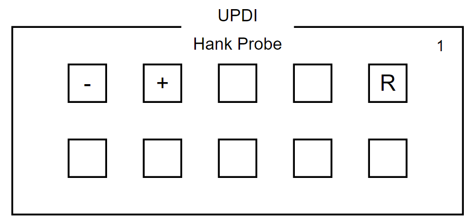
If using Hank’s kit, with the four pin side up, use the first three pins left to
right:
Pogo Pin 1: Top row, far right: R / RX+TX
Pogo Pin 2: Top row, far left: - / GND
Pogo Pin 3: Top row, second from left: + / 3V3
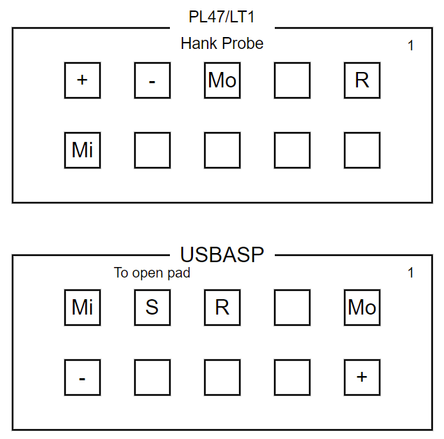
Wiring Diagram for adapting Hank's probe
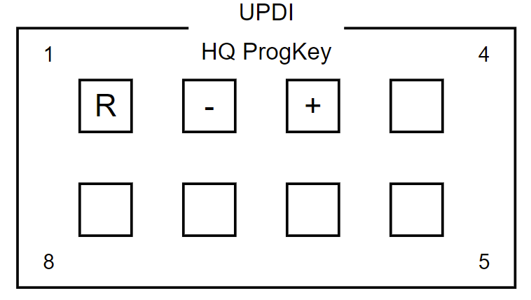
If using a custom adapter, wire the pins up similarly:
1: R / RX+TX
2: - / GND
3: + / 3V3
Wiring Diagram for adapting the HQ ProgKey and similar probes
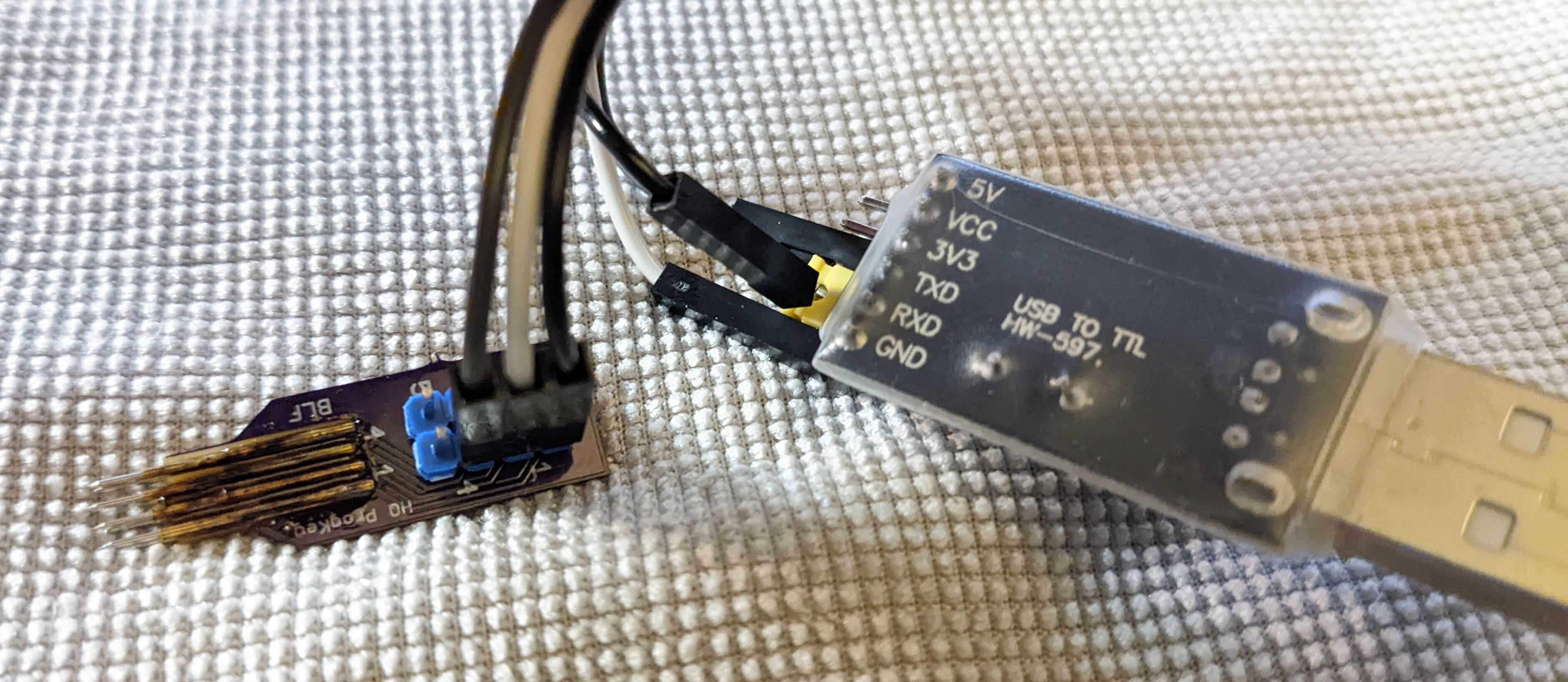
On the CH340 device linked above, the RX and TX pins are separate but they
come with a jumper. The RX/TX wire needs to connect to both pins, which
can be done in a variety of ways. Some people prefer to solder a pin on the
jumper, or solder a wire across both, or connect two wires and splice them into
a single line midway. Personally, I pushed a pogo pin into a Dupont connector
and simply wedged it the opening at the top of the jumper. Pressure from the
neighboring wires keeps it in place and it makes a good enough connection for
this purpose. A similar trick would likely work with a male Dupont connector
end. Soldering is a more reliable and permanent solution, but thus far my
workaround has not
failed.
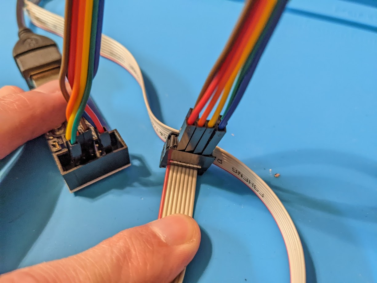
HQ ProgKey connected to CH340. Note the pin through the jumper.
Connecting the Probe to the Light
Unscrew the head from the light and look inside. These lights will have three
pads and they are hopefully labeled properly as either: R - + / + - R.
Align the probe so the pins match the pads.
Install Drivers and Locate the Serial Port
Unfortunately at the moment there isn’t a way to program with these chips from
Android, so use a computer with the right drivers.
This could be Linux, Windows, or macOS. Requirements vary by platform.
Plug the USB device in and let the OS detect it and install drivers.
Windows
On Windows:
Right click the Start/Windows button
Click Device Manager
Expand Ports (COM & LPT)
Locate the port labeled “USB-SERIAL CH340” and note the port listed after
For example COM7.
If there is a ! and the same port is in the list twice:
Double click the “USB-SERIAL CH340” device
Click the Port Settings tab
Click Advanced
Change the device to a different (unused) COM port number
Linux
On Linux, the device will be /dev/ttyUSB<id> for example, /dev/ttyUSB0 . If
there are multiple devices, the correct device is likely the highest one or one
with the newest timestamp.
macOS
On macOS, the device will be /dev/cu.usbserial-<id> , the ID will vary by
hardware. If there are multiple devices, the correct device is likely the one
with the newest timestamp.
Firmware File
Get the correct firmware file, or compile one.
Do a firmware check on the light (15+ clicks, note each digit it flashes) and
compare the date and IDs returned. Last four digits should be the Anduril model
ID. This is mostly for reference in case there is a discrepancy between what the
light was running before and what is loaded after.
There are two ways to update currently, with either avrdude or pymcuprog.
avrdude
The recently released avrdude 7.0
now supports updating through these interfaces and avrdude may already be
familiar for those updating firmware since it is a common way to update other
lights that use USBASP boards.
Download the latest release
Extract it using whatever tool is handy (e.g. Windows Explorer, 7-Zip, or
other file manager or built-in OS utility
Copy the firmware file(s) to the same directory as avrdude to make it easier
Open a command prompt and change to the directory where the contents were
extracted
Ping the Device to Ensure Connectivity
The first thing to try is to ping the device to ensure that avrdude can talk to
both the CH340 device and the target chip. Replace the serial port in the
following command with the port used by the CH340 device:
avrdude.exe: UPDI link initialization OK
avrdude.exe: Device is in SLEEP mode
avrdude.exe: NVM type 0: 16-bit, page oriented write
avrdude.exe: Entering NVM programming mode
avrdude.exe: AVR device initialized and ready to accept instructions
Reading | ################################################## | 100% 0.01s
avrdude.exe: Device signature = 0x1e9421 (probably t1616)
avrdude.exe: Leaving NVM programming mode
avrdude.exe done. Thank you.
If there is an error, most likely the probe was not correctly contacting all of
the correct pins. Check and correct the probe placement and try again.
Read the Old Firmware
A good practice is to read the old firmware in case the new firmware has an
undesirable behavior. That way it’s possible to reload the previous firmware to
get back to the prior state.
After installing python, open a command prompt and install pymcuprog by
running pip install pymcuprog
Fix Python Path
There may be some quirks getting the paths right for pymcuprog if Python was
installed from the Microsoft Store, since the location for the packages is not
in the path by default.
Try running pymcuprog from a terminal, PowerShell, or command prompt, if it
prints its usage output, then it’s OK to proceed. Otherwise, check and correct
the path or python issues.
In Explorer, first locate the correct folder. It will be something similar to
C:\Users\<name>\AppData\Local\Packages\PythonSoftwareFoundation.Python.3.9_<id>\LocalCache\local-packages\Python39\Scripts
– Copy that full path.
The correct path will also be found in the output of
python -c "import sys; print('\n'.join(sys.path))"
it will be the entry similar to the path mentioned previously.
Right click on the Start/Windows button
Click System
Click Advanced System Settings
Click Environment Variables
Find the entry for Path in the User variables section and select it
Click Edit
Add the path to the list (paste it in or type it out)
Click OK, then OK again to close the Environment Variables window
Click OK one more time to close System Properties
Ping the Device to Ensure Connectivity
The first thing to try is to ping the device to ensure that pymcuprog can talk
to both the CH340 device and the target chip. Replace the serial port in the
following command with the port used by the CH340 device:
First, try a ping to see if the device responds to a probe:
pymcuprog ping -d attiny1616 -t uart -u com7
The output should look like the following if it’s successful:
Connecting to SerialUPDI
Pinging device...
Ping response: 1E9421
Done.
If there is an error, most likely the probe was not correctly contacting all of
the correct pins. Check and correct the probe placement and try again.
Erase the Firmware
Unlike avrdude, pymcuprog does not automatically erase before writing, so do a
manual erase:
pymcuprog erase -d attiny1616 -t uart -u com7
The output should look like the following:
Connecting to SerialUPDI
Pinging device...
Ping response: 1E9421
Chip/Bulk erase:
- Memory type eeprom is conditionally erased (depending upon EESAVE fuse setting)
- Memory type flash is always erased
- Memory type lockbits is always erased
Erased.
Done.
Write the Firmware
Change to the directory where the firmware file was downloaded, for example:
cd ~\Downloads
Now write the firmware file. Replace the filename with the correct firmware
filename that matches the light.
Connecting to SerialUPDI
Pinging device...
Ping response: 1E9421
Writing from hex file...
Writing flash...
Verifying flash...
OK
Done.
Factory Reset
After writing the firmware, it’s a good idea to do a factory reset. Hold in the
power button while reassembling the light and let go of the button when the
light goes out.
On some tail switch lights it helps to fully tighten the tube first, then back
it off enough that the aux lights (or main emitter) goes out, then hold the
button while twisting it back fully closed.
See Also
This post was based in part on information from the following threads:
]]>Jim PingleUsing a Raspberry Pi as a Serial Console Server2022-04-02T12:02:41-04:002022-04-02T12:02:41-04:00https://pingle.org//2022/04/02/raspberry-pi-serial-console-serverI have a lot of devices which use serial consoles for my job, most of them with
USB connectors but some with traditional 9-pin serial ports as well. Juggling
connections for all of these can be a chore, but there are ways to simplify the
process.
I have tried several different tactics over the years but the best solution I’ve
found so far is to use a Raspberry Pi as a dedicated serial console multiplexer
(MUX). The title seemed fitting as it takes multiple inputs (serial consoles)
and manages a single output (screen) though the user controls the active input
in this case.
Supplies
Raspberry Pi (or equivalent)
Though this post is geared toward using a Raspberry Pi with Raspbian as a
serial console server, many of the techniques used are general and could be
adapted to a variety of platforms.
USB serial hub with lots of ports
Like this 13-port USB 2.0 hub.
Linux doesn’t seem to get along with lots of USB 3.0 ports and there isn’t any
compelling reason to use USB 3.0 for serial consoles anyhow.
USB serial devices
Varies by device, some have USB consoles, some have serial ports with 9-pin or
RJ45 connectors. Some may require null modem adapters. This is mostly beyond
the scope of what I’m trying to cover here. I’m going to assume you can
already talk to the devices with USB serial in some way.
Speaking of USB serial, I like these USB serial adapters
for devices with regular non-USB serial ports.
GNU screen
GNU screen is capable of talking to serial ports directly, so there is no need
to use a separate terminal emulator program such as minicom. Though if you
prefer to use a different terminal program in each screen or maybe using
tmux, similar tactics should work there, too.
Setup the hardware
Setting up the Pi is out of scope here, I’m going to assume you have a working
pi connected to your network.
Using a wired connection is best for real-time interactive work in SSH, but
depending on your AP and wireless setup it may still work OK that way.
Connect all of the USB serial devices to the hub and connect the hub to the Pi.
To ensure things are probed in the correct and expected order, rebooting the Pi
is a useful measure at this point.
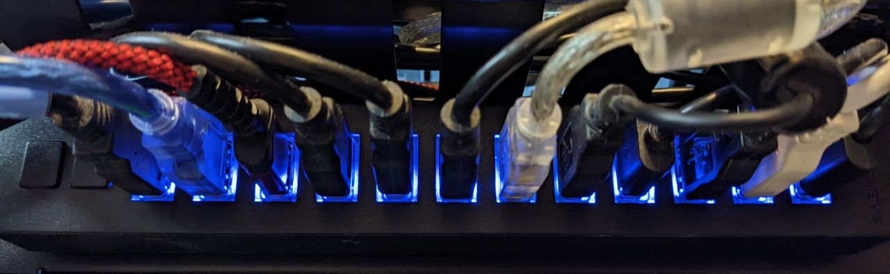
Lots of USB serial connections in one hub
From here on, everything is done over SSH connected to the Pi. Use the SSH
program of your choice (e.g. OpenSSH, SecureCRT, PuTTY).
Map the serial ports to consistent names
Before setting up the consoles let’s take the time to map each port to a
consistent and useful name. Rather than having them numbered, we can set it up
so that each port is labeled after the device. This makes keeping the screen
names and purposes easier to manage over time. If you are lucky and each one has
a unique set of properties, then it won’t even matter which order or ports they
plug into or what order they probe in.
For each of these, go through the device information and find useful and unique
properties which identify a given device. This will give us enough information
to craft udev rules to setup the port names. The command probes the entire
stack to reach the device, but the one you are interested in is usually a few
entries into the output and will look similar to what is shown below.
Replace x in the command with the device number, and repeat the command for
each ttyUSB device.
$ sudo udevadm info --name=/dev/ttyUSBx --attribute-walk[...]
looking at parent device '/devices/platform/soc/3f980000.usb/usb1/1-1/1-1.1/1-1.1.3/1-1.1.3.2':
[...]
KERNELS=="1-1.1.3.2"
ATTRS{manufacturer}=="Silicon Labs"
ATTRS{idProduct}=="ea60"
ATTRS{devpath}=="1.1.3.2"[...]
ATTRS{serial}=="xxxxxx01"[...]
ATTRS{idVendor}=="10c4"
This is an ideal case. The device has a unique vendor ID (idVendor), product
ID (idProduct), and serial number (serial). Not every device will have a
serial number and multiple devices may even have the same serial number, which
complicates matters.
The trickier cases may have to rely on the device path (devpath) which means
they have to remain plugged into the same USB port.
Setup udev rules
Create or edit /etc/udev/rules.d/99-usb-serial.rules and add rules based on
the attributes for each device along with its name.
$ sudo vi /etc/udev/rules.d/99-usb-serial.rules
# These two devices are similar but have unique serial numbers.
SUBSYSTEM=="tty", \
ATTRS{idVendor}=="10c4", \
ATTRS{idProduct}=="ea60", \
ATTRS{serial}=="xxxxxx01", \
SYMLINK+="serial_edge"
SUBSYSTEM=="tty", \
ATTRS{idVendor}=="10c4", \
ATTRS{idProduct}=="ea60", \
ATTRS{serial}=="xxxxxx02", \
SYMLINK+="serial_server"
# These two devices don't have a serial number,
# so we have to use the device path
SUBSYSTEM=="tty", \
ATTRS{idVendor}=="067b", \
ATTRS{idProduct}=="2303", \
ATTRS{devpath}=="1.1.3.7.4", \
SYMLINK+="serial_switch1"
SUBSYSTEM=="tty", \
ATTRS{idVendor}=="067b", \
ATTRS{idProduct}=="2303", \
ATTRS{devpath}=="1.1.3.7.6", \
SYMLINK+="serial_switch2"
# This device has a unique vendor and product ID, but use the serial
# number anyhow in case a similar device is added in the future.
SUBSYSTEM=="tty", \
ATTRS{idVendor}=="0403", \
ATTRS{idProduct}=="6001", \
ATTRS{serial}=="xxxxxx03", \
SYMLINK+="serial_adapter"
Reload and test
Now reload the rules and re-trigger the device detection:
$ sudo udevadm control --reload-rules$ sudo udevadm trigger --attr-match=subsystem=tty
Now look at the mapped devices with our nice names:
These will come back on reboot and when devices are unplugged and replugged.
It’s a good idea to reboot at this point to ensure the custom names return as
expected.
Check privileges
Ensure that your user can access the serial ports. By default in Raspbian the
user is pi and it is a member of the dialout group, and the dialout group
has permission to access the ttyUSB* devices. If you use another user, add it
to the dialout group.
$ sudo usermod -a-G dialout myuser
Alternately, you can run screen through sudo, but that is typically
unnecessary with proper permissions and group memberships.
GNU screen
GNU screen allows a user to run multiple
concurrent terminal sessions from a single login session. This is much easier to
manage than multiple SSH connections to the same server, with the added benefit
that screen can “detach” and leave the terminals connected in the background
while the user does other things or even logs out. Later, the user can resume
the screen session and it is as if they never left.
Many devices will output critical messages to the serial console and if the user
isn’t watching the console when they happen, they can be easily missed. Using
screen with a large scrollback buffer means the user can monitor these devices
and look back at recent output, search it for specific strings, or even write it
out to a file.
Setup screen configuration
Create a configuration file for this dedicated instance of screen:
$ vi .consoles.screenrc
Add in some useful configuration options along with definitions for each of the
serial terminals.
# Handy terminal defaults
termcapinfo xterm ti@:te@
termcapinfo xterm-color ti@:te@
termcap xterm 'is=\E[r\E[m\E[2J\E[H\E[?7h\E[?1;4;6l'
terminfo xterm 'is=\E[r\E[m\E[2J\E[H\E[?7h\E[?1;4;6l'
vbell off
# Status line -- careful the second line is quite long!
hardstatus alwayslastline
hardstatus string '%{gk}[%{G}%H%{g}][%= %{wk}%?%-Lw%?%{=b kR}(%{W}%n*%f %t%?(%u)%?%{=b kR})%{= kw}%?%+Lw%?%?%= %{g}]%{=b C}[%m/%d/%y %C %A]%{W}'
# Misc other defaults
shell -$SHELL
logtstamp on
logtstamp after 1
# No need for the intro screen
startup_message off
# 50000 lines of scrollback per window
defscrollback 50000
# Custom session name
sessionname consoles
# Definitions for each separate screen
screen -t 'Edge' /dev/serial_edge 115200
screen -t 'Server' /dev/serial_server 115200
screen -t 'Switch-1' /dev/serial_switch1 115200
screen -t 'Switch-2' /dev/serial_switch2 115200
screen -t 'Adapter' /dev/serial_adapter 115200
Replace the names, serial devices, and serial port speeds as needed to match
your own setup.
The example above works on GNU Screen 4.x, but GNU Screen 5.x changed the syntax
for colors. I have a separate post about that,
but to keep it short here, use the following status line instead if the host has
version 5:
When screen is running it will display a nice status bar with screen numbers and
the short names we set above with -t <name>.
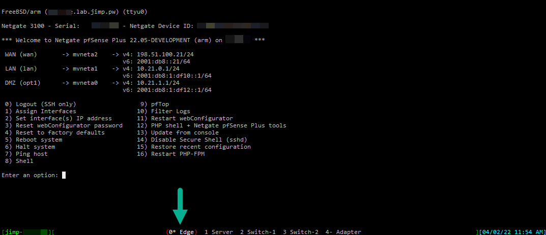
Screen session with multiple windows as configured for this example.
Start screen
This command starts screen using our custom configuration file:
$ screen -c ~/.consoles.screenrc
Resume a screen session that is already running
This command resumes our specially named session (consoles) in multi-display
mode.
$ screen -S consoles -x
In multi-display mode the user can remain connected to the screen from
multiple separate SSH login sessions simultaneously.
Screen commands
The following commands are entered in screen by pressing Ctrl-A (Hold the
Ctrl key and tap the a key), then release both and press the next key. For
brevity, this will be abbreviated like ^A-d for pressing Ctrl-A then d.
^A-d - Detach
Leaves the session running in the background and returns the user to the
shell.
^A-DD (Shift+D twice) - Power detach
Detach and logout in a single step.
^A-a - Toggle next/last screen
Changes between the current screen and the last used screen. If on the first
screen, it switches to the next one. Press again to swap back and forth.
^A-<num> - Switch to a specific screen number
Changes to a specific numbered screen 0-9
^A-n - Next screen
Changes to the next screen in order
^A-p - Previous screen
Changes to the previous screen in order
^A-<esc> - Scrollback buffer mode
Enters scrollback history mode. Moving through the buffer depends on the
terminal program and settings. It may move with arrow keys, hjkl, or even
the mouse scroll wheel. Type ?<string> to search backward, /<string> to
search forward. Press Esc again to exit.
^A-\ - Quit
Terminates screen.
^A-: - Screen command prompt
Accepts a text command from the user. For example, to write the contents of
the entire scrollback buffer to a file, use :hardcopy -h outfile.txt.
^A-? - Help
Displays a help page with a list of commands and other information.
Finish up
With this in place, you can detach from the screen session and leave it running
indefinitely and reattach as needed. This is great for monitoring consoles in
case something goes wrong and prints logs or console messages for debugging.
]]>Jim PingleFlashing a 2020 Sofirn SP36 Pro with new firmware2022-03-27T18:08:41-04:002022-03-27T18:08:41-04:00https://pingle.org//2022/03/27/flashing-a-2020-sofirn-sp36-pro-with-new-firmwareThis post may still be helpful, but I compiled a much more comprehensive
reference site for updating Anduril lights at
https://anduril.click/.
I have an older SP36 BLF from 2020 that was stuck on Anduril 1 while all my
other Anduril lights are on Anduril 2, so I finally decided to rectify that. The
SP36 was the last Anduril light I had left on Anduril 1 as it was also the most
difficult to update.
Since I compulsively write documentation as I go, here are my notes in case
anyone else needs them.
Check the version
There are at least three versions of the board around:
No flashing pads with ATtiny85, which is what I had and what this guide covers
Flashing pads with ATtiny85
Flashing pads with ATtiny1616
The models with flashing pads do not need disassembled the way this guide
describes and the update procedure would be different, closer to the procedure
for updating the LT1.
Before starting, try to do a version check which is 15+ clicks from off. Write
down the result. The last four digits will be a model number which can be looked
up in the list in the MODELS file
and will definitely tell you what it’s running. If the light is running a
version of Anduril before the version check was added, it’s likely the older
variant similar to this guide or at least likely has an ATtiny85 and not
ATtiny1616. If it outputs a date but no 4-digit model code, it’s almost
certainly an older model running Anduril 1.
No matter which model the light is, do a test and a read to save the existing
firmware to confirm the correct settings before attempting to write.
That post has pictures and directions, but to save a click, here is the general
idea:
Unscrew the head from the battery tube
Use needle nose pliers to unscrew the ring retaining the switch
Remove the ring and rubber switch cover
Loosen the switch PCB. If it’s glued you may have to use a tool such as a
dental pick to pry it free. Mine was loose/unglued (lucky me!)
Carefully move the switch PCB out of the way but don’t pull too much on the
wires.
Use an Allen wrench, S hook, bent nail, or similar to put downward pressure on
the PCB through the switch hole
You can see through the switch hole and find a bare spot on the board to
press. Careful not to dislodge the the wiring and careful not to press the
switch wires into the edge of the switch hole as it can damage them.
Carefully pry, the glue will eventually come free, but watch where the tool
will apply pressure.
With the PCB loose, check to make sure nothing was damaged when removing the
board.
I used a 5mm Allen wrench with duct tape covering the end going inside the
light. The advantage of the Allen wrench is you can lift up on the handle and
use the “elbow” of the wrench against the switch hole as a fulcrum rather than
relying on pushing down or hammering. I used a T handle and some socket adapters
to get extra leverage and it popped out after some work.
Something softer than tape on the end might have been better, I scraped the PCB
a little but it was on an empty spot so not critical.
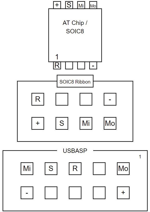
Wire up the adapter
Connect a SOIC8 clip to a usbasp board with jumper wires in the right places
Wiring Diagram for SOIC8 chip, clip, and usbasp board (note location of notches)
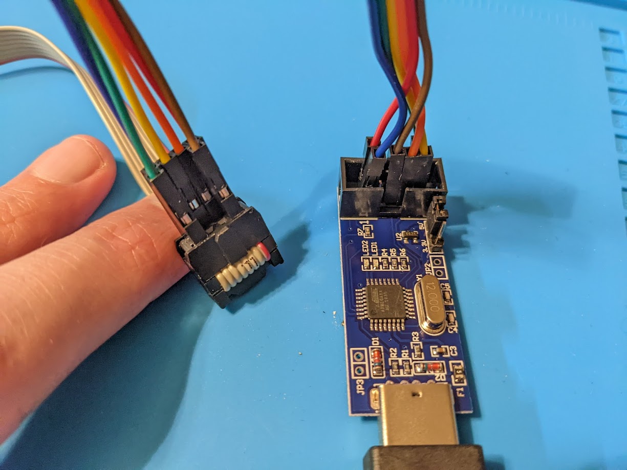
Here are pictures of how I wired up the connection between the usbasp board
and the SOIC8 clip:
Connection from usbasp to SOIC8 clip (front view)
Connection from usbasp to SOIC8 clip (rear view)
I used jumper wires with M-F Dupont connectors so I could leave the original
leads on my SOIC8 clip and plug into its ribbon cable connector.
Connect the SOIC8 clip to the correct chip on the PCB, which is the one
adjacent to the USB port. There is a divot on the chip marking pin 1, see the
pictures and the pinout guide linked above.
As most of these lights can be updated with a SOIC8 clip, after doing this I
crafted a more permanent solution using dupont connector blocks. I used a pick
to release the single dupont connectors from the wire ends and inserted them
into a 2x4 block for the SOIC8 side and a 2x5 block for the usbasp side. This
way I can connect what is now effectively a proper ribbon cable in the future
without having to remember or look up the pinouts.
For older SP36 models this will be sofirn-sp36.hex and for newer models it
may be sofirn-sp36-t1616.hex
Copy the sofirn-sp36.hex hex file to the device which will be doing the
flashing.
Connect the usbasp board to whatever you are using the flash the device. In my
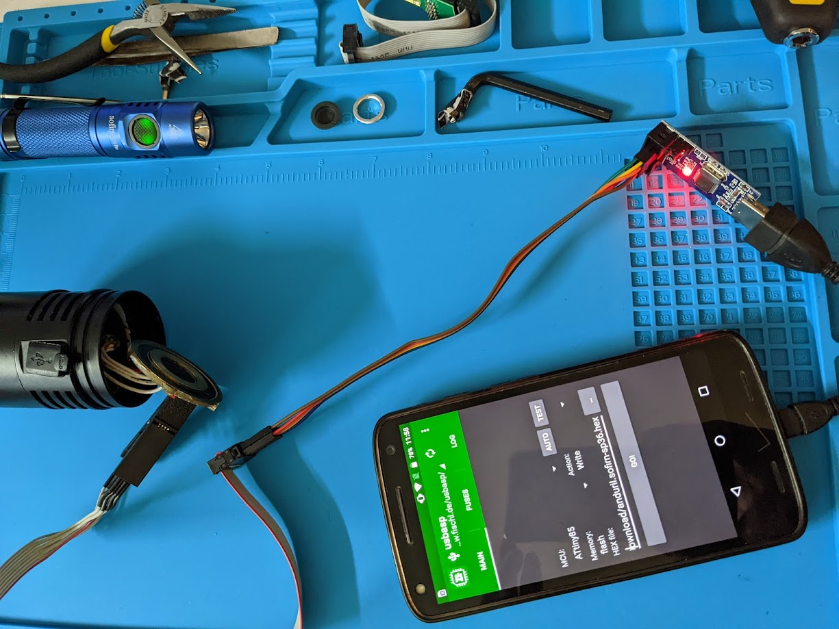
case this was connected to a phone with a USB OTG adapter.
I used zflasher AVR
on Android to perform the update, but there are other ways such as avrdude
or similar programs.
The settings I use for zflasher are:
MCU: ATtiny85 (For newer SP36 models this may be ATtiny1616)
Memory: Flash
Read the existing firmware as a separate file (e.g. sp36-old.hex) and save
it somewhere safe (optional, but a good idea)
Write the new firmware to the chip
Disconnect the SOIC8 clip
Reassemble and finish up
(Optional) clean up some of the glue residue to make getting the board back in
and out easier
Align the board back up using the USB port and side notches as a guide and
gently push it back into place. Odds are it won’t go completely back into
place yet.
Take the batteries out of the tube and screw it back into the head as far as
it can go, which should re-seat the board back in place.
Take the tube back off
Carefully replace the switch, tucking the wires back inside
Replace the rubber switch cover and ring
Tighten the ring back with the needle nose pliers
Put the batteries back in the tube and factory reset
Hold the power button down while tightening the battery tube and keep
holding it for ~4 seconds after it gets power. Repeat if necessary.
Enjoy!
Similar Lights
Slight update, I also have a Sofirn Q8 Pro and BLF LT1. The Q8 Pro does not have
flashing pads, the LT1 had pads but they didn’t line up with any adapter I have
or could make. But in both cases they only had two phillips head screws holding
in the driver board. Remove the screws, the board is loose and it was simple to
gently turn it over and use the same SOIC8 clip method on them that worked on
the SP36.
Line up the USB port and put the screws back in and reassemble, almost easier
than trying to hold an adapter up to the pogo pins while running the update.
]]>Jim PingleFlashing a Fireflies PL47G2 with new firmware2022-03-27T17:07:41-04:002022-03-27T17:07:41-04:00https://pingle.org//2022/03/27/flashing-a-fireflies-pl47g2-with-new-firmwareThis post may still be helpful, but I compiled a much more comprehensive
reference site for updating Anduril lights at
https://anduril.click/.
I recently picked up a Fireflies PL47G2 and didn’t see a flashing how-to out
there for it, so I figured I’d write something up. This may work on other
Fireflies lights but the PL47G2 is the only one of theirs I have so far.
Required Reading
Before starting, read over the guide for flashing the Sofirn
LT1
as the procedure and pin layout is essentially the same. The pin layout on the
LT1 is 3 over 3, the PL47G2 is 3 over 4 but one of the pins on the bottom row
isn’t used.
Adapt the Hank Flashing Kit
I used the flashing kit from
Hank (4 over 2
pinout) so as with the LT1 method it requires adapting the connection to the
different pin layout plus some method of connecting an extra pin. I used a
multimeter lead with a thin probe on one end and alligator clips on the other,
clipped to a similar jumper wire to the ones mentioned in the LT1 thread.
Wiring Diagram for adapting Hank's probe and usbasp board (note the lead that uses a separate wire)
Since writing this originally, I ordered some pogo pins and figured out that
they can push fit into a dupont connector, so when I updated the light again,
I used that instead of a multimeter probe.
Here are the connectors on my flashing kit with the jumper wires in place. The
red wire on the right is going to the multimeter lead.
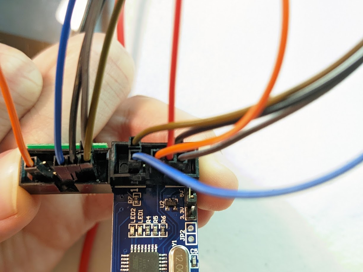
Jumper wires with female to female dupont connectors between usbasp and probe.
If the PL47G2 uses emitters other than Nichia 219, download
ff-pl47g2.hex
If the PL47G2 uses Nichia 219 emitters, use either the pl47-219 variant or
compile a variation of the pl47g2 firmware with the lower FET PWM levels safe
for use with the Nichia emitters.
The pl47-219 firmware disables low aux levels so it’s not ideal for use on
the PL47G2.
I used zflasher AVR
on Android to perform the update, but there are other ways (like avrdude or
similar). I’ll stick to zflasher, though.
Copy the .hex file somewhere on the phone/tablet accessible to the app (e.g.
Downloads directory).
Connect the phone/tablet to the flash kit (e.g. using USB C to A Female adapter
or OTG cable)
Open the app and set it up as follows:
MCU: ATtiny85
Memory: Flash
Action: Write
Load the hex file with the firmware
Screenshot of zflasher with the correct settings.
Connect the Pins
Line up pogo pins on the flashing kit such that one pin on the row of 4 is
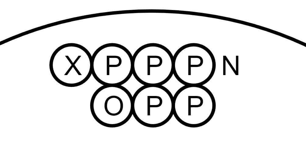
NOT touching anything. Should be like so:
Pin layout inside the light head with notations for adapted probe
X is an open pad that is not used
P is a pad touched by a pogo pin
N is a pogo pin not touching a pad
O is an open pad which is where the extra lead goes (multimeter for me)
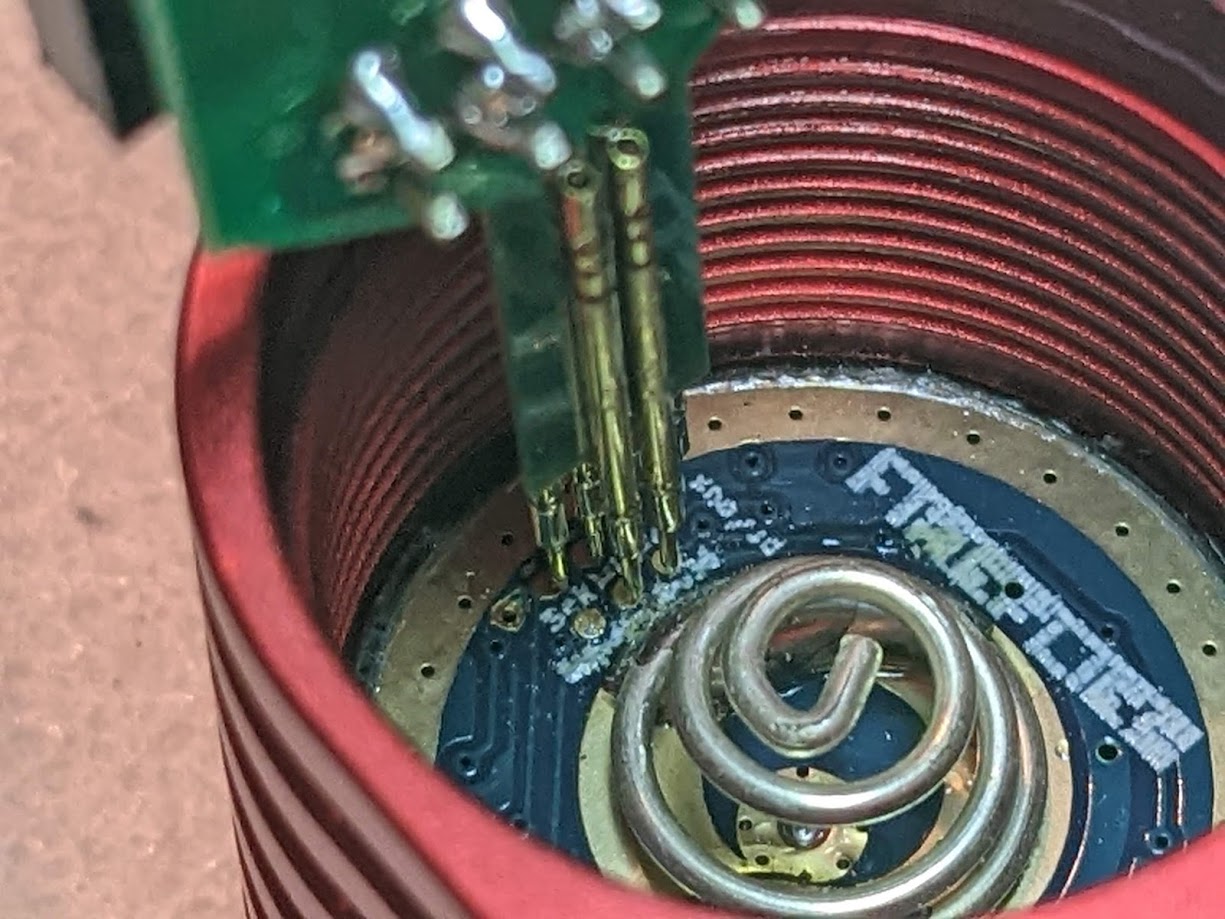
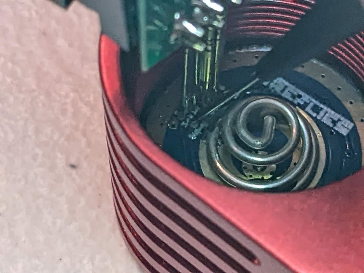
Flashing kit pins making contact in the correct place.
Flashing kit with the extra multimeter lead connected.
Test and Update Firmware
In the app, run a test first. If it fails, fix the error and try again. Most
likely it wasn’t making contact with all the pins.
If the test succeeds, then write and wait for it to write and verify.
Final Thoughts
Bonus shot of the cobbled together setup to make it happen, with a guest
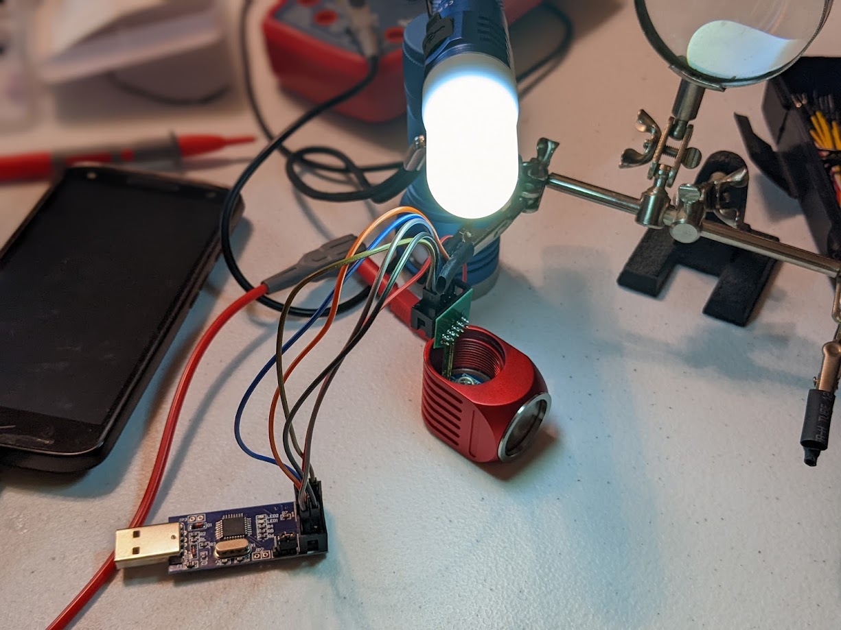
appearance from a D4Sv2 and SC31 Pro working together as a little task light:
Overview of the setup used to update the firmware.
HQ ProgKey / Other USB ASP Boards
I ordered a couple batches of these HQ ProgKey
PCBs from OshPark to make an adapter I could use for these Fireflies lights.
I used some solder paste to reflow pogo pins
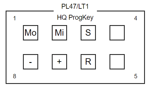
and connecting pins onto the adapter and then wired it up to match the pin
layout.
Wiring Diagram for HQ ProgKey and usbasp board
Pin layout inside the light head
I had some trouble initially getting it to work, but as it turns out the problem
was the usbasp boards I had purchased from Amazon. The adapter works fine with
the board from Hank’s flashing kit, so I’ll keep using that for now.
]]>Jim PingleRewiring the Heated Bed on a Monoprice Select Mini v2 3D Printer2017-10-08T23:07:41-04:002017-10-08T23:07:41-04:00https://pingle.org//2017/10/08/rewiring-the-heated-bed-on-a-monoprice-select-mini-v2-3d-printerRecently I acquired a Monoprice Select Mini v2 3D Printer and I’ve been having a
great time learning and experimenting with 3D Printing on it. It’s a wonderful
little printer that is inexpensive (At around $220), puts out great quality
prints, it’s easy to work with and to work on. That said, it has a fatal flaw in
its design: The wiring for the bed heater and thermistor is routed along a
horrible path that lets the wires rub against the gears moving the bed, and
these two pairs of wires are zip tied in a place that makes them kink as the bed
moves. Between these two problems, the wiring is prone to short, fray, or break
entirely. Unsurprisingly, I had to repair mine, read on to find how how.
A visit to the Monoprice Select Mini Facebook
group or the
subreddit shows a surprising (to
me, at least) number of people with related problems.A common chorus when
discussing the printer is “rewire the bed before you do anything else”. It can
manifest as the bed heater not working or the bed temperature readout being
incorrect, typically reading 999 or 0.
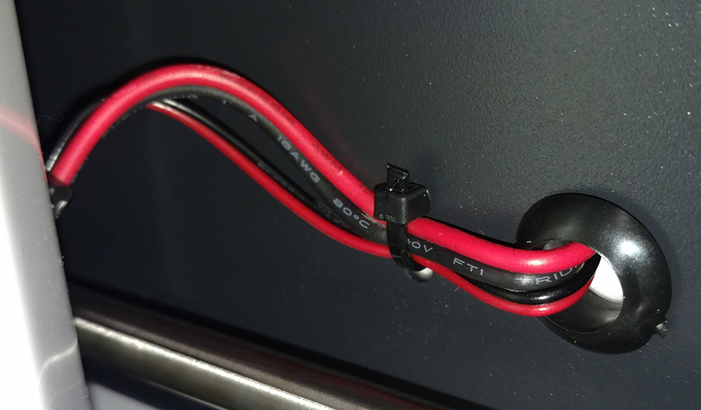
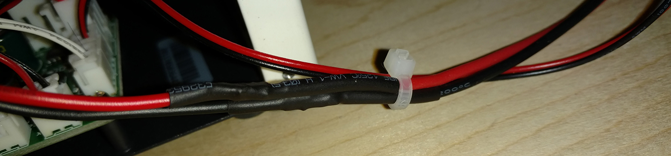
Wires get pinched by this zip tie and bend at that point as the bed moves
Since mine had been OK, and I’d owned it less than a month, I figured I had
time. I was wrong. After a couple weeks and a non-trivial number of printing
hours, the bed wouldn’t preheat. The temperature readout was OK, but it read
about room temperature and didn’t move. I canceled the print, went into the
printer’s monitor screen and had it preheat the bed. Still nothing. I knew the
wires could be the problem so I moved the bed back and forth to see if it would
kick in, and it did when I moved it all the way forward. Move the bed back and
it stopped. Classic short behavior, so I knew what I was in for. Now I had two
choices: One: Send the printer back and get it fixed or repaired, or two: Fix it
myself. Option one meant I’d be without the printer for probably a week or two
and when it came back it would still have a bad wiring job. Option two means I
could have it up and running in a couple days at most, and I could use a better
wiring path that wouldn’t be prone to breaking. I opted to fix it myself, but I
didn’t have all the parts on hand which is why it took a couple days to fix.
While waiting for the parts to arrive I watched some videos on
youtube by others who made similar
repairs, but I did not want to drill through the case, so I also researched some
other options. Once it all arrived it was actually a very straightforward fix,
so I documented it all and here it is!
Requirements
I chose to do a no-drill method using a printed side panel to reroute the wires.
I do not want to have to deal with the mess of metal shavings that drilling
would cause. The directions below assume this method, plus also rewiring the
heater connection. Here are the parts I printed to replace the side panel and
help run the wires:
Cable brace: https://www.thingiverse.com/thing:1937513
– I used the second version, and mirrored it in Cura so the hole was on the
correct side for the side mount cable path
Tools
You’ll need these tools to either reroute the wiring or to repair the bed wires
Use the Move menu to raise the Z axis a few inches up to have clearance to
remove the bed
Remove side panel where SD socket and USB connector are, the wires plug in
just behind here.
Cut the zip ties along the bed wires inside and outside the unit, you might
have to remove the bottom panel for easier access, if so, lay the printer down
on its side with the removed side panel end facing up.
Identify the bed wires: there are two pairs of wires, a thicker pair for the
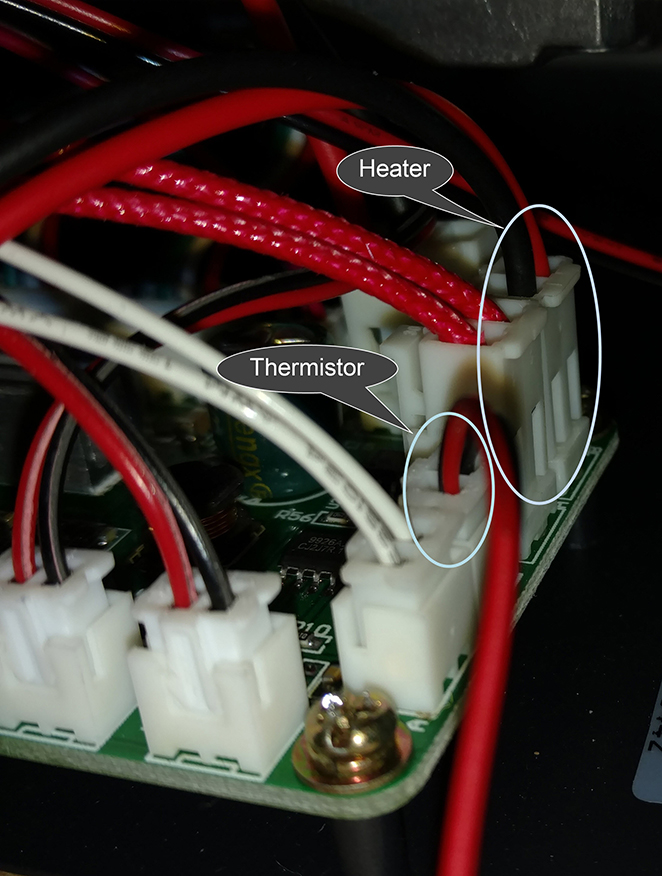
bed heater, and a thinner pair for the bed thermistor. Follow them and locate
where they run and where they are plugged into the controller board. The
heater wires have a larger white connector on the board, the thermistor is a
smaller white connector near the open side panel.
Mark and/or snap a photo of the connectors so you know which side is red and
which is black, and where they plug in
Disconnect the bed wires from inside the unit
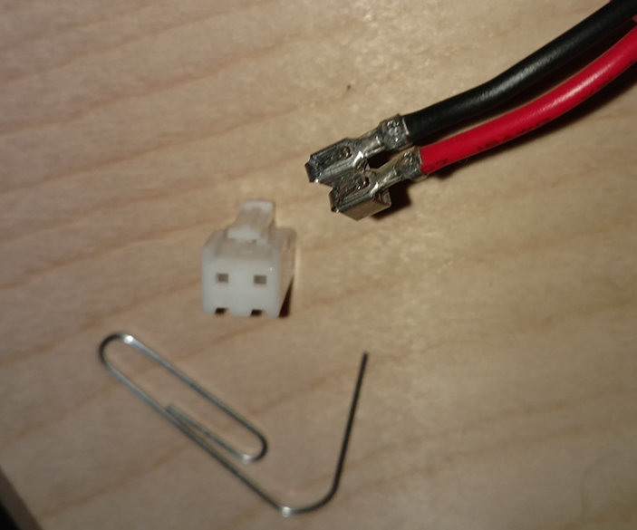
Carefully remove the connector from the end of the heater wires (thicker
wires, larger connector) so the wires can be backed out through the grommets.
You may not need to do this depending on whether or not you can wiggle the
connector through. It is much easier to move the wire without the lump of a
connector on it, and it’s not hard to remove the connector, only need
something with a fine point to push in the little catch on each wire, like a
pin, paperclip, or sharp tweezers.
Move the wiring back through the grommets so it comes right off the back of
the heated bed and not through the body of the printer or the carriage
If you do not need to repair the wires, skip ahead to Rewire part 2.
Repair the wires
Carefully back out all of the bed leveling screws and set the screws, caps,
and springs aside. Don’t lose any pieces!
At this point the bed is completely separated from the printer so it can be
moved it to a better work area, I reattached the connector to the heater wires
to keep them together but it will need to be off later to go through the cable
sleeve, so it’s up to you.
Using a multimeter I confirmed my red heater wire had a nasty short. The black
wire was fine, but I replaced them both anyhow.
Mark which connection is positive and which is negative on the bed, and/or
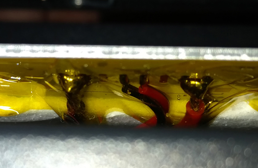
take a picture for reference
Remove the Kapton tape covering the solder connections on the bed
Carefully desolder the thick heater wires from the bed (outer wires): Hold the
soldering iron tip on the solder bead until it reflows and then they come
right off
Cut the connector end of the wires off, keeping a few inches of old wire to
splice into later so you can reuse the connector
Cut two lengths of new 18AWG silicone flexible wire: One red, one black,
really the color isn’t important, but it’s good to match.
Strip a bit off both ends of the new wire and the salvaged connector wires
Solder one end of each new wire to the bed in the appropriate spot
Put some 1” Kapton tape back over the solder connections. Preferably use new
Kapton tape, not old, but the old may be tacky enough to reuse.
Put some heat shrink tubing around the wire to be used after splicing
Mesh or twist the new and salvaged wire ends together
Solder each pair of wires together to form a strong bond
Move the heat shrink tubing so it completely covers the solder on each wire
with room to spare
Melt the heat shrink tubing using a high heat source. I used a heat gun, but a
lighter or torch works
If you need to replace the thermistor wires, repeat this procedure again for
those, but with appropriate AWG replacement wire
Replace the bed, using the screws, springs, and caps to reattach it
You will definitely need to relevel the bed after, but don’t do that yet
Rewire Part 2
Better than new
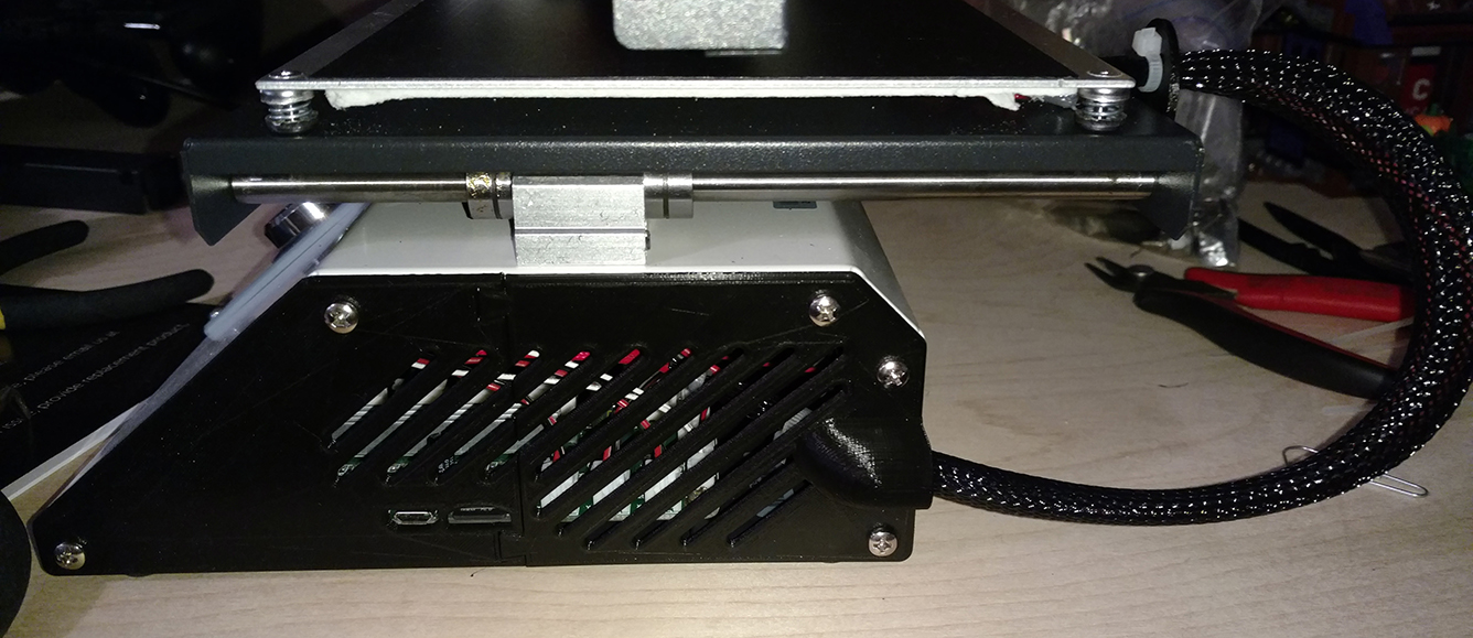
Run the bed wires through the hole in the cable brace
Attach the cable brace on the back of the bed carriage. It needs screws, I
used some old PC case screws that fit.
Slide the wire through some sort of conduit – braided cable sleeve, spiral
tube wrap, cable chain, etc. The connector on the heater wires will probably
need to be off for it to fit, unless you use spiral wrap which can fit around
anything.
Put a zip tie at either end of the conduit, for example I used braided cable
sleeve so I put a zip tie between the bed and the cable brace, and another
just before the connectors
Put the heater wire connector back on if it was removed, and reconnect the
heater and thermistor to the main controller board
Put on the new side panels – If you couldn’t print new side panels because
you need the heated bed, just leave the side panel off while you print
replacements!
Relevel the bed and try preheating it
For me, the bed heated right up to 60C where I wanted it, and my prints are back
to sticking like I’m used to!
All done!
If you choose to do a method involving drilling or if you choose a different
side panel configuration, the last few steps may need to change to route the
cables through whatever new path is available.